
How to install: Battery operated Roller Shutters
This section will guide through the installation process of our Domestic, Cyclone, Security and Light Commercial range of shutters, the process is almost the same for all four shutter types, with modification needed to the Cyclone and Light Commercial and Security, which is listed at the bottom of this page.
Battery installation is more difficult than installing Electric
Tools required:
- Spirit level.
- Drill.
- Hammer.
- 10mm drill bit.
- 5mm drill bit.
- 5 or 6mm Masonry drill bit depending on wall plug size chosen, and Stainless Steel screws to suit. For timber frame windows, just Stainless Steel screws.
- Battery components: 1 head box, 2 guides, 2 guide legs, 10mm coloured guide plugs and rivets, 1 battery charger, and 1 battery controller.
Step 1.
Charge your battery. This will take some time approximately 8-10 hours for a full charge, so if you start this as soon as you receive your order, it may be ready by the time you start the installation process.
Step 2.
Mark the top horizontal position of the Roller Shutter on the wall above the window. On this line mark the width of the shutter. From these 2 marks, vertically level down each side of the window. You will now have the outline of the Roller Shutter marked on the wall. At this stage you can check that it is central to the window and is exactly horizontal and vertical — This Is Most Important!
Step 3.
Measure the depth of the head box. Then from the top horizontal position of the Roller Shutter which you have marked on the wall, measure this distance down each side. This will then give you the position for the top of the guide on each side of the window.
Modification required for the Cyclone Roller Shutters
The HDF-R Restrained Guide must be modified, this should be done at (this procedure is not on the video see link below) HDF Restrained Guide must be modified.
For In-Reveal You can
now cut the guide to the exacted length, and angle of the sill.
Step 4.
Hold the guide in the 2 positions marked. Top of guide position (as in step 3) and the vertical guide position (as in step 2).
You can now mark the best position to fix the guide to the wall and these marks can be transferred to the other side guide.
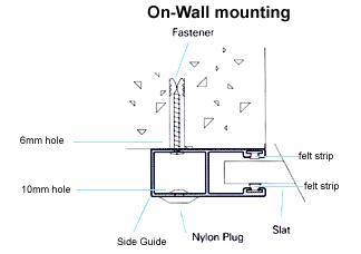
You can now drill through the front and back of the guide; the drill size is determined by the size of Stainless Steel screw you use. The front of the guide will need a 10mm hole in which the 10mm coloured guide plugs are inserted – this then covers up the fixing points.
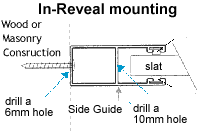
For In-Reveal:
The fixing holes are drilled from the curtain side 10mm to the outside 5mm. No 10mm coloured plug is required.
Step 5
From inside the house find the desired position of the controller, then transfer this position to the outside wall behind the guide. Then drill through the wall. This hole is for the cable to the wall plate
Step 6.
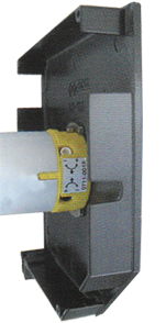
The head box comes with pre-drilled holes to attach the head box cover after installation. The guide legs can now be slid into position, (die cast legs that fit onto the bottom corner of each side of the Head box, and connect the main assembly to the guides) remove the rubber rings first that hold the plastic box end insert, this box end insert helps guide the curtain from the head box down into the guides. Then slide the guides on each side leg. Carefully place the Roller shutter on the outline of the marked on the wall and mark your fixing points and cable hole. Then drill and plug the wall if masonry; if it is a timber wall, just a pilot hole to suit the fixing screws. On the back of the guide drill a large hole to allow the cable to exit the guide.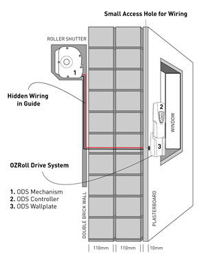
Step 7.
At the end of the shutter that has the ODS, you will see that the guide leg has a hole, which must be drilled right through. Remove the rear rivet and feed the cable through the guide leg and then down the guide to the cable exit hole. Then replace the removed rivet.
Step 8.
Carefully place the Roller shutter next to the window. Through the cable hole in the wall insert a piece of wire, then attach the cable from the motor to the wire and start pulling the cable into the house. Raise the Roller shutter to the outline marked on the wall, and then screw it to the wall.
On-Wall Installation: Then insert the 10mm coloured guide plugs.
Step 9.
Unwrap the curtain and place the bottom bar of the curtain into the guides on each side – they will click into position.
Please note: The curtain will not move, until the motor has power to turn the axle.
Step 10.
The cable can now be clipped into the wall plate, and fixed to the wall.
When the controller is fully charged, place it in the wall plate and check the operation of the curtain. If the curtain runs in the opposite direction to the indicated arrow, swap the wires around on the wall plate
Roller Shutters under 3.5 square meters in size, It is most commonly fitted with the L10 battery motor this motor is preset in the factory will automatically stop at the fully closed and open positions.
By pressing the centre button on the controller, it will stop at any desired position.
If your Roller shutters is over 3.5 square meters in size and some roller shutter under 3.5 square meters, will be fitted with the T20 or the T35 battery motor, this battery motor requires the up and down stop limits to be set.
T20 and T35 Battery Motor Up and Down limit setting instructions.
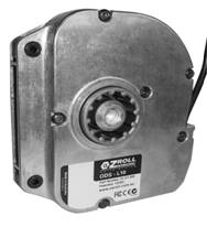
Below are photos of the L10, T20 / T35 Battery Motors
Please note: If the shutter height limit is not set correctly, the bottom bar of the curtain has a bottom bar V stopper each side, which stops the curtain from going completely into the head box, but this causes the motor to jam and stop, this should be avoided and the up limit set to stop the curtain before this happens.
Please note: The Box Locking System must be set at the correct position. Please read
The Box Locking System and the Slat locking System
Step 11.
When the curtain is in the down position you will be able to fix the head box to the wall, this should be done on each side through the head box end plate.
Step 12.
Box End Entry Roller – Kit This is only supplied with Extra Large shutters in the Cyclone, Security, and Light Commercial range, this will not be supplied with smaller shutters in the range. Box End Entry Roller – Kit modifications.
Step 13.
Rivet the head box cover on and you are done!
Please note:
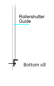
Although 90% of windows have sills, if your windows don’t, then don’t despair! We have a solution to that.
We can supply a false sill for the curtain to fully close down on.
The aluminium sill can be the same colour as the head box and guides and come in 3 sizes
24mm x 22mm $6.00
24mm x 46mm $8.50
24mm x 77mm $12.00
To order a sill send an email and request a sill immediately after you place your order
I will then send you a PayPal request for payment.
Modification required for the Cyclone, Light Commercial, and Security.
Cyclone Modifications: The HDF Restrained Guide must be modified, this should be done at Step 2 (this procedure is not on the video see link below) HDF Restrained Guide must be modified.
Cyclone Modifications: To comply with the Cyclone Rating the shutter must be fitted with a Bottom Guide to the full width of the exposed curtain, allowing the curtain bottom bar section to close down into the bottom guide section, Step 3. This information and other fixing requirements can be found at this link, a must read item. Australian Standard AS / NZS 1170.2 – 2002
Box End Entry Roller – Kit This is only supplied with Extra Large shutters in the Cyclone, Security, and Light Commercial range, this will not be supplied with smaller shutters in the range. Box End Entry Roller – Kit modifications.